- What is a Class Diagram?
- Main Components of a Class Diagram
- Relationships in Detail of a Class Diagram
- How to Draw a Class Diagram?
- Full Example
What is a Class Diagram?
A class diagram describes the structure of a system by showing the system’s classes, their attributes, and the relationships between the classes. It serves as a blueprint for designing and understanding software projects.
- We use the class diagram to model the static structure of a system, thus describing the elements of the system and the relationships between them.
- These elements and the relationships between them do not change over time.
- A class diagram partitions the system into areas of responsibility (classes) and shows “associations”(dependencies) between them.
- The class diagram is without doubt the most widely used UML diagram.
- It is applied in various phases of the software development process.
- The level of detail or abstraction of the class diagram is different in each phase
- Class diagrams can be presented at three distinct levels, or perspectives:
- Conceptual: the diagram represents the concepts in the project/business domain.
- Specification: shows interfaces between components in the high-level design stage.
- Implementation: shows classes that correspond directly to computer code/implemented system (often Java or C++ classes).
Main Components of a Class Diagram
- Class: Represents a blueprint for an object. It’s depicted as a rectangle with the class name at the top, followed by attributes and methods. A class describes a group of objects with:
- similar properties (attributes),
- common behaviour (operations),
- common relationships to other objects,
- and common meaning (“semantics”).
- Attributes: Variables that hold data.
- Methods: Functions associated with the class.
- Modifiers: They are used to indicate visibility of attributes and operations.
+is used to denote Public visibility (Visibility: everyone)#is used to denote Protected visibility (Visibility: friends and derived)-is used to denote Private visibility (Visibility: no one)
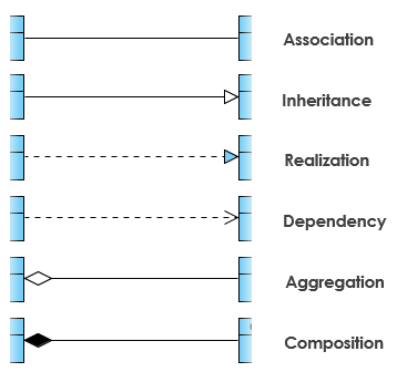
- Relationships: Including associations, generalizations (inheritance), and dependencies.
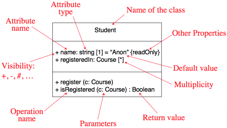 The full notation of Class
Relationships in Detail of a Class Diagram
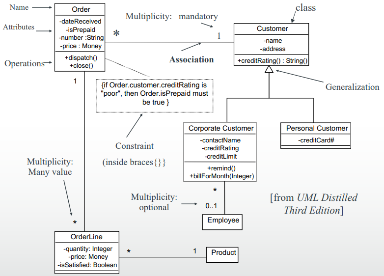
- Association: Represents a “has-a” or “using” relationship between two or more classes.
- There is an association between two classes if an instance of one class must know about the other in order to perform its work.
- An association has two ends. An end may have a role name to clarify the nature of the association. For example, an
OrderDetailis a line item of eachOrder. - A navigability arrow on an association shows which direction the association can be traversed or queried. An
OrderDetailcan be queried about itsItem, but not the other way around. - The arrow also lets you know who “owns” the association’s implementation; in this case,
OrderDetailhas anItem. Associations with no navigability arrows are bi-directional.
- Aggregation: Represents a “whole-part” relationship. The part can exist independently of the whole.
- Class2 is part of Class1.
- Many instances (denoted by the *) of Class2 can be associated with Class1.
- Objects of Class1 and Class2 have separate lifetimes.
- Composition: A “strong” form of aggregation. The part cannot exist without the whole. It is binary association, part could be included in at most one composite (whole) at a time, and if a composite (whole) is deleted, all of its composite parts are “normally” deleted with it.
- Objects of Class2 live and die with Class1.
- Class2 cannot stand by itself.
-
Generalization (Inheritance): Represents an “is-a” relationship. An inheritance link indicating one class is a superclass of the other.
-
Realization: This relationship is used to depict the realization of UML interfaces by UML classes. It means that one entity (usually a class) implements the behavior specified by another entity (typically an interface). It’s represented by a dashed line with a hollow arrowhead pointing from the implementing class to the interface.
- Dependency: Indicates that one class depends on another.
The difference between Association and Dependency in UML:
- Association:
- Nature: Association represents a bi-directional, structural link between two classes, suggesting that there’s a long-term relationship between them.
- Lifetime: Objects at both ends of an association may have similar lifetimes, or one object’s lifecycle might be independent of the other. For instance, if you have a
Teacherclass and aStudentclass, an association might suggest that aTeachercan be associated with multipleStudents, and vice versa.- Usage: Often used to depict relationships like “has-a”, suggesting one class contains or is linked to another.
- Dependency:
- Nature: Dependency represents a temporary, unidirectional relationship. It indicates that one class (the dependent or client) relies on another (the supplier) for some functionality or behavior, but it’s not a long-term relationship.
- Lifetime: In a dependency relationship, the lifetime of the dependent is often independent of the supplier. The relationship only suggests that at some point, the dependent class may use the supplier.
- Usage: Common in cases where a class uses another transiently, such as a
method parameter,local variable, or in amethod invocation. Dependency suggests a weaker relationship compared to association and hints at the idea that a change in the supplier might affect the dependent class.
How to Draw a Class Diagram?
- Identify Classes: Start by listing down the entities.
- Add Attributes and Methods: For each class, define its attributes and methods.
- Define Relationships: Determine how each class interacts with others.
- Finalize the Diagram: Ensure that all relationships and elements are correctly captured.
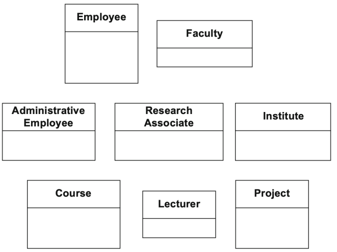
Example: How to Draw a Class Diagram of “Information system of a university”
- A university consists of multiple faculties which are composed of various institutes. Each faculty and each institute has a name. An address is known for each institute.
- Each faculty is led by a dean, who is an employee of the university.
- The total number of employees is known. Employees have a social security number, a name, and an e-mail address. There is a distinction between research and administrative personnel.
- Research associates are assigned to at least one institute. The field of study of each research associate is known. Furthermore, research associates can be involved in projects for a certain number of hours, and the name, starting date, and end date of the projects are known. Some research associates teach courses. They are called lecturers.
- Courses have a unique number (ID), a name, and a weekly duration in hours.
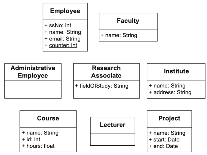
Identifying the classes
Identifying the attributes
Identifying the relationships between classes
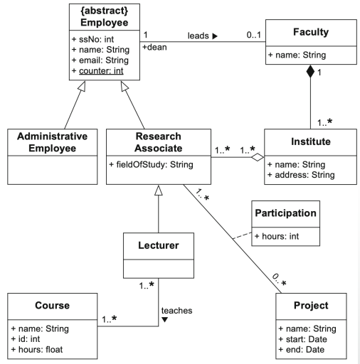
Full Example