
- What is Data Modelling?
- Database Design
- Graphical Representation (ERD) of Data Modelling
What is Data Modelling?
- Data modelling is a technique for organising and documenting system’s DATA.
- Data modelling is sometimes called database modelling because a data model is usually implemented as a database. It is sometimes called information modelling.
- Many experts consider data modelling to be the most important of the modelling techniques.
Why is Data Modelling Considered Crucial?
- Data is viewed as a shared resource to be used by many applications.
- As a result, data must be organised in a way that is flexible and adaptable to unanticipated business requirements.
- Data structures and properties are reasonably permanent
- Certainly a great deal more stable than the applications that use the data.
- Often the data model of a current system is nearly identical to that of the desired system (new system).
-
The process of constructing data models helps analysts and users quickly reach consensus on business terminology and rules.
- Poor design leads to the following software flaws:
- Poor response time and hence poor performance
- Redundancies and difficulty in system maintenance
- Data omissions and integrity problems
- Security and reliability problems
- Pressure on the programming effort to compensate for the poor design.
- Lack of clarity and inflexibility
Some Objectives of Database Design
- Efficiency and flexibility
- Reliability, security and protection
- Control of redundancy
- Consistency and Accuracy
- Ease of access and ease of change
- Data independence — immunity of application programs to structural, storage or hardware changes of the database
- Clarity and multi-user access
Approaches to Data Modelling
- There are two approaches database design:
- Conventional files
- Database approach which includes
- Relational model
- Object-oriented model
- Hierarchical model
- Network model
- Non-relational models
Database Design
-
For database design, the relational model and the OO model are the two which are adopted by contemporary software engineering. But In recent years, non-relational model has gained huge popularity.
-
Steps involved in designing a relational or OO database:
- Identify data entities or object types
- Identify relationships
- Eliminate unnecessary relationships
- Develop an entity-relationship diagram (ERD) or an object-relationship diagram (ORD)
- Prepare the database tables’ specification
- Develop and implement the database
Difference Between ERD and ORD
An Entity-Relationship Diagram (ERD) and an Object-Relationship Diagram (ORD) are both visual tools used in database design, but they serve different purposes and represent different aspects of a database system.
- Entity-Relationship Diagram (ERD):
- ERDs primarily focus on modelling the data structure of a database. They emphasize entities (tables), attributes (columns), and the relationships between entities.
- ERDs are effective at illustrating how data is organized and related.
- ERDs are commonly used in the context of relational databases, where data is organized into tables with rows and columns. Relationships in ERDs are often defined using foreign keys.
- ERDs are widely used in traditional relational database design and are helpful for designing systems where data storage and retrieval are the primary concern.
- Object-Relationship Diagram (ORD):
- ORDs primarily focus on objects and their relationships. Object-oriented databases store data as objects, where each object may have attributes and methods, and these objects are interconnected.
- ORDs are designed to depict how objects are structured and how they interact with one another.
- ORDs are used for object-oriented databases, where data is stored in the form of objects. These objects can have complex structures and behaviors, making ORDs more suitable for representing the intricacies of object-oriented data.
- ORDs are used in scenarios where the focus is on modelling complex, interconnected objects and their behaviours, such as in object-oriented databases and software systems that leverage object-oriented programming principles.
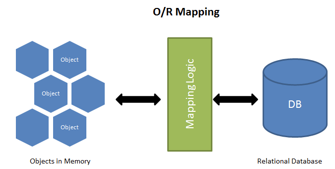
Object-Relational Mapping (ORM)
- Object Models can be Mapped to relational databases using Object-relational mapping (ORM) approaches.
- ORM is a technique for converting data between object-oriented world and relational database systems.
- Object-Relational Mapping (ORM) is a programming technique and technology used in software development to bridge the gap between the object-oriented programming (OOP) world and the relational database management system (RDBMS) world.
- ORM systems provide a way to work with databases in a more object-oriented manner, allowing developers to use programming languages and objects to interact with the database, rather than writing raw SQL queries and dealing with the intricacies of relational databases.
-
Popular ORM frameworks and libraries include Hibernate (for Java), Entity Framework (for .NET), Django ORM (for Python), and Sequelize (for JavaScript/Node.js), among others. These frameworks are widely used in building web applications and other software systems where the integration of a relational database is required.
- ORM can significantly simplify database interaction and make code more maintainable, but it’s essential to have a good understanding of the underlying database and ORM framework to use it effectively, as there are trade-offs to consider in terms of performance and complexity.
Advantages of ORM
- Simplifies Database Interactions: ORM allows developers to work with objects and classes in their programming language, abstracting away the need to write complex SQL queries. This simplifies database interactions and reduces the amount of SQL code that developers need to write.
- Database Portability: ORM frameworks often support multiple database management systems (DBMS). This means you can write database code that is relatively independent of the specific DBMS, making it easier to switch between different databases if needed.
- Faster Development: ORM can speed up the development process by eliminating the need to write and maintain extensive SQL code.
- Security: ORM frameworks often include security features, such as automatic parameterized queries, which help prevent SQL injection attacks.
- Maintainability: ORM can make code more maintainable because it abstracts the database structure, reducing the impact of database schema changes on the application code.
Disadvantages of ORM
- Performance Overhead: ORM can introduce performance overhead because it generates SQL queries dynamically, which may not be as efficient as hand-optimized queries. This can be a concern in applications with high-performance requirements.
- Learning Curve: Learning how to use an ORM effectively can take time, as developers need to understand the ORM framework.
- Complex Queries: ORM frameworks may struggle with complex or non-standard database queries. Writing complex queries or stored procedures might still require raw SQL, which can be less convenient.
- Possible Abstraction Leaks: In some situations, the abstraction provided by ORM frameworks might not perfectly match the database model, leading to a leaky abstraction.
- Lack of Control: Developers might have limited control over the generated SQL queries, which can be a problem in situations where fine-tuned control over query optimization is essential.
Graphical Representation (ERD) of Data Modelling
There are several notations for data modeling, but the actual model is frequently called an Entity Relationship Diagram (ERD).
An ERD depicts data in terms of the flowing graphical elements:
- Entities
- Attributes
- Relationships
Entities
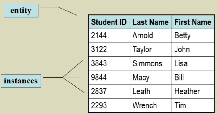
- All systems contain data and data describes ‘things’
- A concept to abstractly represent all instances of a group of similar ‘things’ is called an entity.
- An entity is a class of persons, places, objects, events, or concepts about which we need to capture and store data.
- An entity has a set of attributes to describe it
- An entity drawn as a labeled rectangle in ERD
Entity Examples
- Occurrence or events (e.g., phone call)
- Thing (e.g., report or display)
- Role (e.g., salesperson)
- Organizational unit (e.g., accounting department)
- Place (e.g., warehouse)
- Structure (e.g., File)
- External entity (anything that produces or consumes information)
Entity and instances
Attributes
- The pieces of data that we want to store about each instance of a given entity are called attributes.
- An attribute is a descriptive property or characteristic of an entity.
- Synonyms: element, property, and field.
- Some attributes can be logically grouped into super-attributes called compound attributes.
- A compound attribute is one that actually consists of more primitive attributes.
- Synonyms : concatenated attribute, composite attribute, and data structure.
Types of attributes
- Simple attribute (e.g : name.)
- Composite attribute: consists of a hierarchy of attributes. (e.g.: address. It contains number, street, postcode, etc.)
- Multivalued: same instance can have different values. (e.g.: degree. Everyone can have multiple degrees: bachelor, master, PHD)
- Derived: an attribute whose value is computed from other attributes (e.g.: age. It can be calculated from the birthday.)
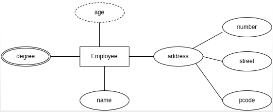 Different types of attributes in ERD
Key of Attributes
-
One or more attributes must be defined as identifier: “key” to find an instance of the entity. (e.g. ID number of a student).
- Sometimes more than one attribute is required to uniquely identify an instance of an entity.
- A group of attributes that uniquely identifies an instance of an entity is called a concatenated key.
- Synonyms: composite key, compound key.
- Frequently, an entity may have more than one key.
- Each of these attributes is called a candidate key.
- A candidate key is a ‘candidate to become the primary identifier’ of instances. (Note: A candidate key may be a single attribute or a concatenated key.)
- A primary key is that candidate key which will most commonly be used to uniquely identify a single entity instance.
- Any candidate key that is not selected to become the primary key is called an alternate key.
- In a relational database, a foreign key is a database constraint used to establish a link between two tables.
- It ensures that the values in a column or a set of columns in one table match the values in a primary key or a unique key in another related table.
- The purpose of foreign keys is to maintain consistency and relationships between related tables, which helps in structuring and organizing data in a relational database.
Sub-setting Criteria of Attributes
Sometimes it is also necessary to identify a subset of entity instances rather than a single instance.
- For example, we may require a simple way to identify all male students, and all female students.
- A sub-setting criteria is an attribute (or concatenated attribute) whose finite values divide all entity instances into useful subsets.
- Some methods call this an inversion entry.
Relationships
- Associations between instances of one or more entity types that are of interest
- The relationship may represent an event that links the entities, or merely a logical affinity that exists between the entities.
- Drawn as line between entities, labeled with verb phrases
- A verb phrase describes the relationship.
- All relationships are implicitly bidirectional, meaning that they can be interpreted in both directions.
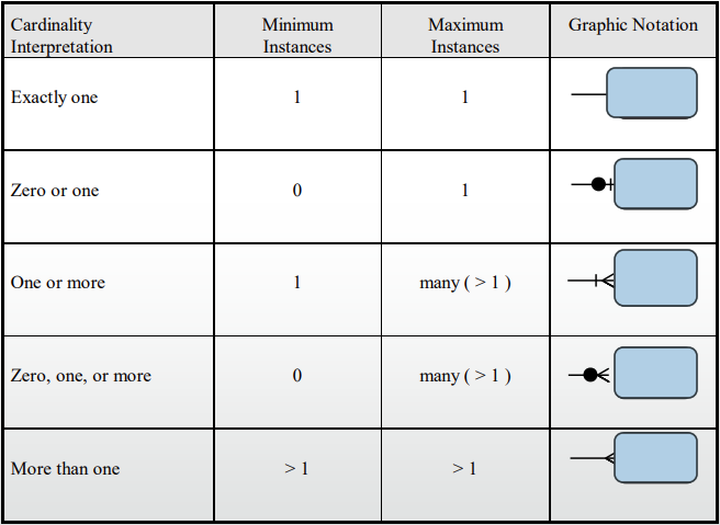
Cardinality of Relationships
- Specification of the number of occurrences of one object that can be related to the number of occurrences of another object
- Possible relationships:
- One-to-One: Each entity in the relationship will have exactly one related entity
- One-to-Many: An entity on one side of the relationship can have many related entities, but an entity on the other side will have a maximum of one related entity
- Many-to-Many: Entities on both sides of the relationship can have many related entities on the other side
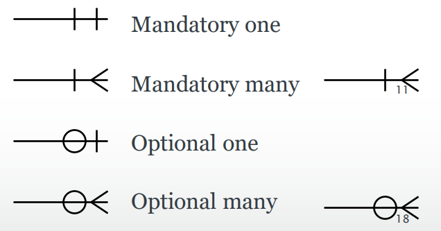
Modality of Relationship
- Specifies whether the relationship is optional or mandatory
- Modality is 0 if relationship is optional
- represented by dotted line in ERD
- Modality is 1 if relationship is mandatory
- represented by straight line in ERD
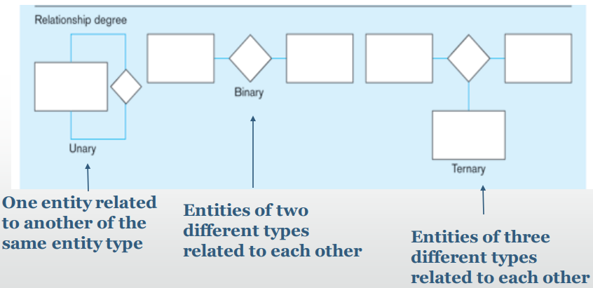
Degree of Relationship
The Degree of a relationship is the number of entity types that participate in it.
Cardinality Constraints
Cardinality Constraints: the number of instances of one entity that can or must be associated with each instance of another entity
- Optional: If zero or more, then optional.
- Mandatory: If one or more, then mandatory.
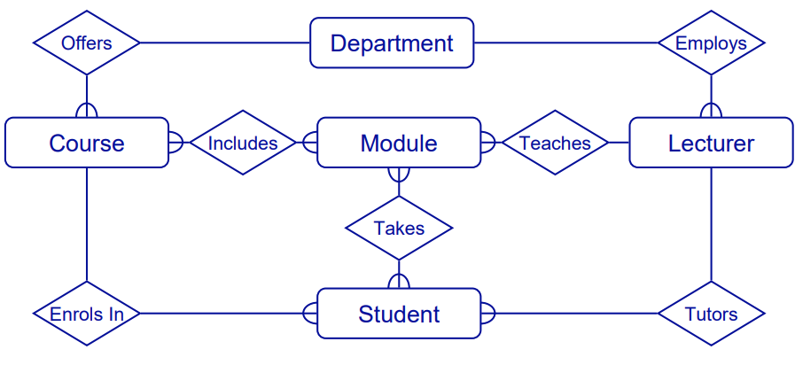
Different Representation of a Relationship
Examples of EDR
 Student-Course
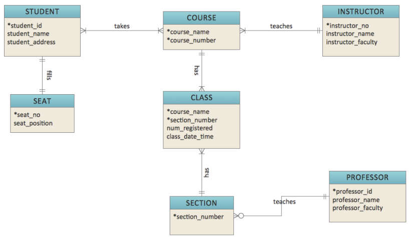 Student-Course
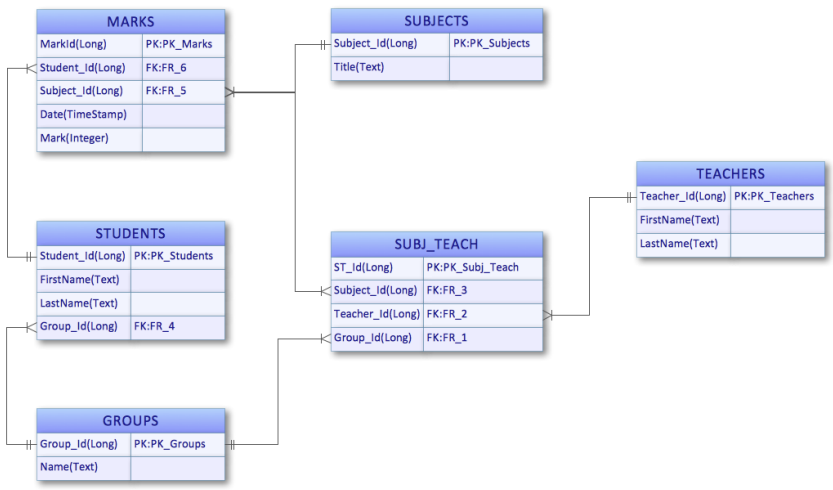 Student-Course (PK: primary key, FK: foreign key)
