When we delve into the intricacies of system interactions and object collaborations, Sequence Diagrams in Unified Modeling Language (UML) emerge as a pivotal tool.
- What is a Sequence Diagram?
- Key Components of a Sequence Diagram
- Notations of a Sequence Diagram
- How to Create a Sequence Diagram
- Advantages of Sequence Diagrams
- An example of Sequence Diagrams
What is a Sequence Diagram?
A Sequence Diagram in UML is a type of interaction diagram that shows how objects operate with one another and in what order. It is a form of a dynamic model that delineates the sequence of messages exchanged between objects and components to carry out a specific functionality or a process.
- A tool to document the behaviour within use cases.
- Sequence diagrams are popular with both business analysts and system designers.
- Sequence diagrams represent the detailed interaction between actors and a system or between collaborating objects within a given time block.
- However, messages shown in the sequence diagram can have preconditions and postconditions. These conditions are not directly visible in the diagram.
Key Components of a Sequence Diagram
-
Objects and Classes: These are the entities that interact with each other, depicted at the top of the diagram.
-
Lifelines: These are vertical dashed lines that represent the existence of an object over a period.
-
Deletion: These are ‘X’ placed at the end of the lifeline, which represent object’s life ends at that point.
-
Activation Bars: These are thin rectangles that show the time period an object is active and performing an operation.
-
Messages: These are arrows that represent the communication between objects, displaying the sequence of interactions.
-
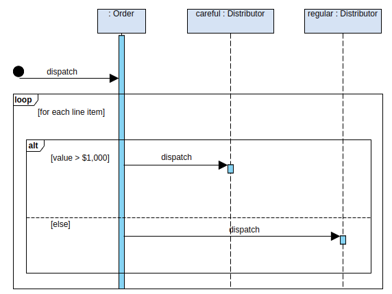
Loops and Conditions: These are constructs that represent repetition and conditional behavior in the interactions.
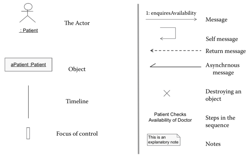
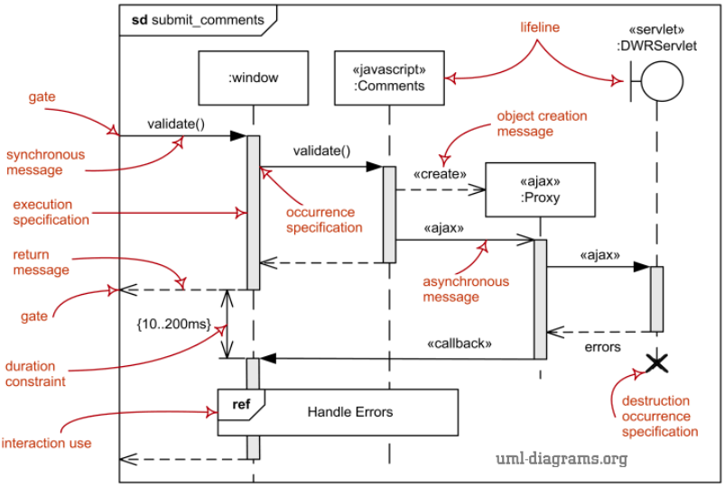
Notations of a Sequence Diagram
How to Create a Sequence Diagram
-
Identify Objects and Classes: Determine the objects and classes that will be part of the interaction.
-
Draw Lifelines: Draw the lifelines for each object or class.
-
Add Activation Bars: Place activation bars where the objects are active.
-
Insert Messages: Draw arrows to represent the messages exchanged between objects, in the order they occur.
-
Include Loops and Conditions: Add loops and conditions as needed to represent repetitive and conditional interactions.
Advantages of Sequence Diagrams
-
Clarity: They provide a clear visualization of the order of interactions between different objects or components.
-
Traceability: They help in tracing the sequence of events that occur in a system.
-
Facilitates Communication: They serve as an effective means of communication among team members, ensuring everyone has a clear understanding of the system interactions.
-
Aids in Testing and Debugging: They are instrumental in testing and debugging by outlining the expected flow of messages and interactions.
- You should use sequence diagrams when you want to look at the behaviour of several objects within a single use case.
- Sequence diagrams are good at showing collaborations among the objects.
- They are not so good at precise definition of behaviour.
An example of Sequence Diagrams