
In the realms of computer science and formal verification, Symbolic Model Checking stands as a crucial technique, especially in verifying complex systems like digital circuits and software programs.
- What is Symbolic Model Checking?
- Explicit versus Symbolic Modelling of Software Systems
- Symbolic Modelling of Systems
- Symbolic Model Checking
- BDDs and Symbolic Model Checking
What is Symbolic Model Checking?
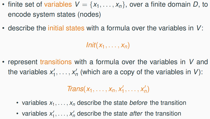
Symbolic Model Checking is an approach used in the field of formal verification to prove or disprove properties of a system (often hardware or software) modeled formally with mathematical objects. Unlike traditional model checking that enumerates all possible states of a system, symbolic model checking uses mathematical symbols to represent and explore state spaces efficiently.
The Birth and Evolution of Symbolic Model Checking
Symbolic Model Checking emerged in the 1980s as a response to the limitations of explicit state model checking. The primary challenge was the state explosion problem, where the number of states grows exponentially with the number of components in a system. Symbolic approaches, particularly those utilising Binary Decision Diagrams (BDDs), offer a way to compactly represent and manipulate large state spaces.
Key Components of Symbolic Model Checking
-
Model Representation: The system model is often represented using Kripke structures or similar formalisms, encompassing states and transitions.
-
Property Specification: Properties to be verified are specified using temporal logics like CTL (Computation Tree Logic) or LTL (Linear Temporal Logic).
-
Symbolic Algorithms: Algorithms that manipulate symbolic representations, like BDDs, to explore possible states and verify the specified properties.
Explicit versus Symbolic Modelling of Software Systems
Explicit Modelling:
- transition systems model software systems explicitly
- each node represents a system state
- each edge represents an atomic state change
- this suffers from state space explosion
- the number of states grows exponentially with the number of variables
- a system with n Boolean variables can have 2^n states
- so, transition systems are inadequate to model systems with more than a few variables
Symbolic Modelling:
- in contrast, symbolic model checking avoids explicitly constructing the state space of a system, and instead represents it as a formula in propositional logic
- this allows for compact representations, e.g. using Binary Decision Diagrams (BDDs)
Symbolic Modelling of Systems
Represent a System Symbolically
Boolean Connectives and Notation
- boolean connectives: ¬ (not), ∨ (or), ∧ (and), → (implies), ↔ (if and only if, means that the result is
truewhen the values of the two variables are the same, andfalsewhen they are different.) - V = {v1, . . . , vn} set of boolean variables
Symbolic Representation of Systems
Example: Noughts and Crosses

- Variables and Domain:
- Variables:
V = {x1, . . . , x9, t}. Domain(value of Variables):D = { –, X, O, A, B } - variable
xiencodes the content of celli–stands for empty cellXstands for marked by player AOstands for marked by player B
- variable
tencodes the player who moves next (A or B)
- Variables:
An explicit representation of the state space would use ≈ 40000 states!
- Initial configurations:
- Init:
(x1 = −) ∧ (x2 = −) ∧ . . . ∧ (x9 = −) ∧ (t = A ∨ t = B) - (all cells are empty and either player A or player B can start)
- Init:
- Transition relation:
- (either player A or player B can move, if it is her turn, and mark one of the empty cells)

- Winning condition for player A (B is similar):

Represent a Program Symbolically
1
2
3
int x,y = 0,0;
while (true)
  x,y = (x+1) mod 3, x+1;
- variables:
x,ywith domainint(bounded!)

Boolean Programs
- in the previous examples, the domains(values) for the variables are not Boolean
- to encode
InitandTransas propositional logic formulas, we would need to encode each program variable using several boolean variables - to avoid doing this (for convenience), we restrict to Boolean programs:
- only Boolean variables
- only ASSIGNMENT, IF, and WHILE statements
- no procedure calls
How to Represent a Boolean Program?
Example of a Boolean Program:
1
2
3
4
5
6
7
8
9
10
11
12
begin
L1 : x1 = false;
L2 : while (x1 ∧ x2) do
L3 :    x1 = true;
L4 : endwhile;
L5 : if (x1 ∨ x2) then
L6 :    x1 = x1 ↔ x2;
L7 : else
L8 :    x2 = x1 ↔ x2;
L9 : endif
L10 :
end
(L1 - L10 is program counters)
Program counters
Lrepresents the position where the previous statement finished executing, it does not mean that the next statement is going to be executed.For example:
L7means:x1 = x1 ↔ x2has finished executing, the next step should breakifdirectly. So, the next ofL7should beL10!L7doesn’t means:elseis going to be executed. So, the next ofL7should not beL8!It is important to understand this description. Otherwise, looking at the following Encoding example is going to be confusing.
- variables:
V = {x1, x2, PC}
- domain:
D = {F, T, L1, . . . , L10}- still not Boolean!
- transitions:
- Trans = ?
It seems hard to get Trans, so let’s look at a few simple examples first:
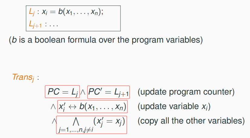
Example of Encoding assignments Trans
Example of Encoding if-then-else statements Trans

Example of Encoding while statements Trans

Trans of Previous Example

How do We Encode PC = Li as A Boolean Formula?
Representation on the previous slide is still not a Boolean formula! We need to encode PC = Li as a boolean formula.
- assume the values of the program counter (L1, . . . , L10 in the previous example) can be represented using n bits (4 in the example)
- use Boolean variables
pc0, . . . , pc_n−1to encode the value of the program counter- e.g. use variables
pc0, pc1, pc2, pc3to encode integersi ∈ {1, . . . , 10}(and thus the formulaPC = Li). For example:i= 6 (i.e.0110in binary), the formulaPC = L6is encoded as(pc3 ↔ 0) ∧ (pc2 ↔ 1) ∧ (pc2 ↔ 1) ∧ (pc3 ↔ 0)
- e.g. use variables
Similar encodings can be done for programs with variables of types other than Boolean!
Symbolic Model Checking
A Simple Example
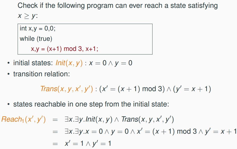

Computing Reachable States

Checking Safety Properties

Checking LTL Properties

BDDs and Symbolic Model Checking
- binary decision diagrams (BDDs) are a canonical form to represent Boolean functions
- often more compact than traditional normal forms
- can be manipulated efficiently
- reachable state space can be represented as a BDD
- property verification uses iterative computations on the reachable state space
