- What is a Use Case Diagram?
- Key Concepts in Use Case Diagrams
- How to Draw a Use Case Diagram
- Example
- Possible Mistakes with Use Case Diagrams
What is a Use Case Diagram?
Use Case Diagram:
- A generalised description of how a system will be used.
- Provides an overview of the intended functionality of the system
A Use Case Diagram is a visual representation that shows the interactions between external actors and the system to achieve a particular goal. It helps in understanding the external functionalities and requirements of a system.
- Use-cases are a scenario-based technique in the UML which identify the actors in an interaction and describe the interaction itself.
- Each use case represents a discrete task that involves external interaction with a system.
- Actors in a use case may be people or other systems.
- Represented diagrammatically to provide an overview of the use case and in a more detailed textual form.
Key Concepts in Use Case Diagrams
-
Actors: These are entities that interact with the system. They can be users, other systems, or external processes. They are typically represented by stick figures.
- Use Cases: These are specific actions or functions the system performs in response to an actor. They are represented by ovals.
- A use case is a single unit of meaningful work. (e.g. login, register, place an order, etc.)
-
System boundary: A rectangle diagram representing the boundary between the actors and the system.
-
Relationships: Lines or arrows depict the interactions between actors and use cases. There are several types of relationships in use case diagrams:
-
Association: A simple line connecting an actor to a use case, indicating that the actor participates in the use case.
-
Include: Depicted by a dashed arrow with the label “«include»”. It indicates that one use case (the base) includes the behavior of another use case.
-
Extend: Shown by a dashed arrow with the label “«extend»”. It indicates that the behavior of a use case can be extended by another use case, usually under certain conditions.
-
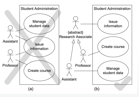
Generalization: A solid line with a hollow triangle arrowhead. It indicates that one actor or use case inherits the properties and behaviors of another.
-
others: Used when exceptional circumstances are encountered.
-
How to Draw a Use Case Diagram
- Identify Actors: Start by determining who or what will interact with the system.
- Identify Use Cases: List down the specific actions or functions the system will perform for the actors.
- Connect Actors and Use Cases: Draw lines or arrows to show which actor initiates which use case.
- Define Relationships: If there are any “include”, “extend”, or “generalization” relationships, depict them appropriately.
- Organize and Refine: Ensure the diagram is clear, with use cases logically grouped if necessary.
Example
Let’s consider a library management system:
The library lends books to borrowers who must have a valid library card. An item is borrowed by scanning it and the library card on a self-service machine. The librarian periodically purchases new titles for the library. For popular titles more than one copy is purchased. A borrower can reserve a book online even if it is not currently available. Once the reserved book is available(returned or purchased) the borrower is notified. The librarian should be able to remove old titles.
- Actors: borrower, librarian, and self-service machine. In this case library is not an actor or can be replaced by librarian
- Note since the library can have multiple copies of the same book we need to differentiate between an item (copy) and a title
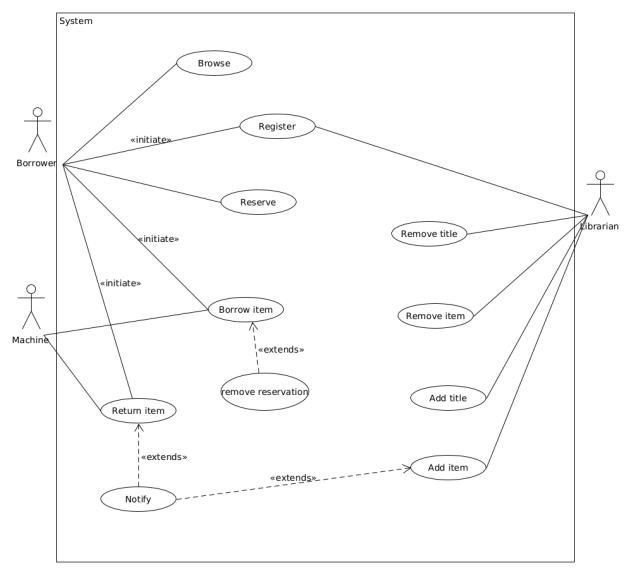 One possible use case diagram
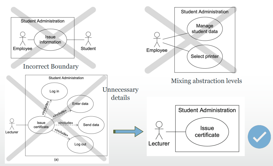
Possible Mistakes with Use Case Diagrams